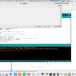
I’m getting ready to use my Bluefruit Feather in a big project, well, big to me anyways. Before I do that, however, I needed to test a few things to make sure that I understand how it works. So, I added to my “cylon eye” sketch that I made last time, to include communication via serial (over USB) and taking an analog reading over pin A0. Here’s my sketch:
int brightness = 0; // how bright the LED is
int fadeAmount = 5; // how many points to fade the LED byvoid setup() {
pinMode(LED_BUILTIN, OUTPUT);
// initialize serial communication at 9600 bits per second:
Serial.begin(9600);
}void loop() {
analogWrite(LED_BUILTIN, brightness);// change the brightness for next time through the loop:
brightness = brightness + fadeAmount;// reverse the direction of the fading at the ends of the fade:
if (brightness <= 0 || brightness >= 80) {
fadeAmount = -fadeAmount;
}
// wait for 30 milliseconds to see the dimming effect
delay(100);
// To print the brightness // Serial.println(brightness);// read the input on analog pin 0:
int sensorValue = analogRead(A0);
// Convert the analog reading (which goes from 0 – 1023) to a voltage (0 – 3.3V):
float voltage = sensorValue * (3.3 / 1023.0);
// print out the value you read:
Serial.println(voltage);
}
I simply modified the Arduino sketch and added it to my already made cylon eye sketch. The user interface on this thing is incredibly easy! All I am doing here is setting up the USB to accept serial input at a baud rate of 9600 (plenty fast enough for the tiny bits of information I am transmitting). Then I take a reading off of pin A0, which comes off of the center tap of a 100k pot. The positive and ground are provided from the boards own 3.3 volt dc supply and ground pin, respectively.
Now I need to test if I can use this as a multi-meter. I grabbed a D cell battery and used my handy dandy alligator clips to hold everything in place. So on my potentiometer, I attached the left side to the negative terminal on the battery, and the right side to the positive side of the battery. The center tap of the pot still goes to the A0 pin, but now, I am not connected to the 3.3 volt dc supply on the board. However, to make this work, you need a common ground, so I still have the board ground hooked to the negative terminal of the battery. Cycling the pot revealed my results, spanning from 1.45 to 0 volts dc!
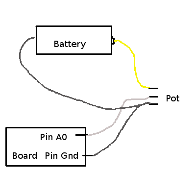
Try not to laugh too hard at my quick sketch, I just wanted to make sure that you understood what I was saying. Think of pin A0 as the red wire of your multi-meter, and pin ground as the black wire of your multi-meter.
So far, so good. I still need to test a few more things before I can move forward with my project. Perhaps in my next post I can outline the details of what I hope to accomplish.
Linux – keep it simple.